")
Currently no blog post for this video
This is the discussion topic for the video and blog post linked above. Please keep all replies relevant to the content, otherwise create a new topic.
Currently no blog post for this video
This is the discussion topic for the video and blog post linked above. Please keep all replies relevant to the content, otherwise create a new topic.
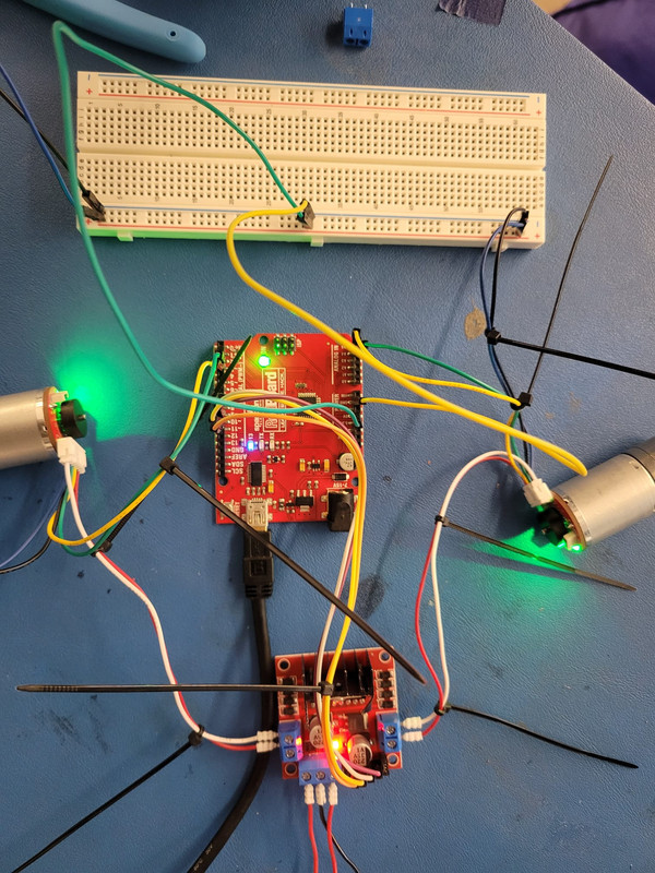
Hi, I’ve ran into an issue trying to get miniterm to work. I’m having trouble discerning the issue and how to resolve it (error is below). any help would be much appreciated. i have basically all the same hardware as in the video (raspi 4 model B, arduino nano, L298N driver).
Note: my pi wasn’t recognizing the ‘miniterm’ command so found a workaround as depicted below. I’ve also added the user to the dialout group.
jon@jon-pi:~$ python3 -m serial.tools.miniterm -e /dev/ttyAMA0 57600
— Miniterm on /dev/ttyAMA0 57600,8,N,1 —
— Quit: Ctrl+] | Menu: Ctrl+T | Help: Ctrl+T followed by Ctrl+H —
Exception in thread rx:
Traceback (most recent call last):
File “/usr/lib/python3.10/threading.py”, line 1016, in _bootstrap_inner
self.run()
File “/usr/lib/python3.10/threading.py”, line 953, in run
self._target(*self._args, **self._kwargs)
File “/usr/lib/python3/dist-packages/serial/tools/miniterm.py”, line 499, in reader
data = self.serial.read(self.serial.in_waiting or 1)
File “/usr/lib/python3/dist-packages/serial/serialposix.py”, line 549, in in_waiting
s = fcntl.ioctl(self.fd, TIOCINQ, TIOCM_zero_str)
OSError: [Errno 25] Inappropriate ioctl for device
Ok, after a day of troubleshooting, I finally figured out the issue. Posting the solution to others if they get here…
For one, AMA0 isn’t the right address. This took a bit of work to find, but I used the following command to find which USB address my Pi was assigning to the Arduino by using the following command on the Pi:
sudo dmesg | grep ttyUSB
This command showed that my Pi was assigning the Arduino to ttyUSB0 (just like in the tutorial) whenever I plugged in or unplugged the arduino. GREAT!
HOWEVER - this wasn’t the only issue. I was still unable to get miniterm to connect successfully. It would say ‘[Errno] No such file or directory’.
So, I used the following command to monitor what happens when I plug in the arduino:
sudo dmesg --human --follow
And it showed that the system was disconnecting my arduino from ttyUSB0 as soon as it was plugged in, and gave the following error:
usbfs: interface 0 claimed by ch341 while 'brltty' sets config #1
It seems that some utility called BRLTTY was interfering with the connection, so I used the following commands to disable BRLTTY in the ssh terminal on the Pi:
for f in /usr/lib/udev/rules.d/*brltty*.rules; do
    sudo ln -s /dev/null "/etc/udev/rules.d/$(basename "$f")"
done
sudo udevadm control --reload-rules
sudo systemctl mask brltty.path
[Thanks to this stack exchange answer]
Then restarted the Pi, and the arduino was staying connected to ttyUSB0, miniterm worked as expected, and my motor came to life!!
In the end, the miniterm command that worked for me after disabling BRLTTY was:
python3 -m serial.tools.miniterm -e /dev/ttyUSB0 57600
Just came on to reply to your original message and saw you got it solved.
That seems like quite an ordeal, so well done for solving it and I really appreciate you posting your solution here for others to find in the future!
Glad it’s sorted ![]()
Hey Josh, I seem to be getting some weird behavior on the encoder for the left motor using the miniterm bridge. I consistently get good encoder readings on the right motor but not the left (pins A4/A5). I’ve swapped the motors, replaced the motors, and checked that I’m getting good oscillations using an oscilloscope on the encoder pins, but miniterm only ever says -1, 0, 1, or 2 for the left motor (even if I swap the motors). Any ideas what could be going on? I suspect there’s something going on in the code but it’s a pretty complex for me to debug. Thanks!
I think in my head I had replied to this one but apparently not! (That seems to be happening a bit lately)…
That’s very strange, and someone on the Discord server seemed to have a similar issue (which I believe they have not resolved).
What model Arduino are you using?
hi ,
I am running the following command in Pi using SSH terminal.
ros2 run serial_motor_demo driver --ros-args -p serial_por:=/dev/ttyUSB0 -p loop_rate:=30 -p encoder_cpr:=3450
that command is run but when i run the the command ( ros2 run serial_motor_demo gui ) it shows the gui but not running the motor.
and while running the miniterm -e, the encoder values is different while running the same speed. what can i do ??
Hi guys, I’m working on a project in which I’m using the differential drive concept to control two brushless motors connected to their own ESCs, I thought I’d be able to control the ESCs via ROS but I’ve been unsuccessful so far since ros-serial doesn’t work in foxy, and I can’t use micro-ros because the Arduino board I’m using isn’t supported. Will I have to revert back to ros1 for this project? or is there another way I can get ros and my Arduino to communicate? Thank you.
Sorry for the very late response, but your code has serial_por instead of serial_port - if that was copied directly, could that be the issue?
Did you ever resolve it?
Hey! You can definitely still do this with ROS 2, it just might take some fiddling.
My recommended approach would be to use ros2_control (check out my other videos on the topic). Especially check out my recent video on writing a custom hardware interface. You should be able to write your own hardware interface that speaks to an Arduino via serial and send whatever commands you want. (I’m assuming from your post that you already have an Arduino communicating via serial).
Alternatively, you could write a node from scratch (in this case I’d recommend python and check out my serial_motor_demo) that subscribes to the Twist topic and directly communicates with the Arduino using Python serial libraries (or other methods if appropriate).
Hope that helps, feel free to ask for more clarification ![]()
Thanks for your response, I don’t have my Arduino communicating over serial yet, that’s what I’m trying to get figured out but I’ll go over your ros2_control videos again, the main issue is the fact that I’m using an ESC and not a motor driver, this has kept me stuck for a while because I can’t get encoder values or send PWM signals via miniterm. Thank you.
Has anyone rewrote the diff_drive_arduino to use with brushless motor drivers?
my motordrivers are just a bit different - I only pull the DIR_PIN high or low to change direction of the wheel, so i made a slight change in the arduino code but now it does not recognize the direction.
strange thing is… the code (isolated to only the arduino part) works perfect when running it from the arduino IDE serial monitor.
Hey Jon, I am facing a similar issue. I too have tried everything you have tried - did you solve this issue? I’m using an Arduino Uno instead of an Arduino nano
Hey Gaurang, yes I did. It turned out to be bad encoders on the motors. And actually, the motors I have look very similar to yours. Did you get them off of Amazon? I would buy a few extra motors and swap them out to see if you start getting good readings. I’ve learned that the encoders on these cheap motors have very high defect rates (or they get shorted and fried really easily), so buy more than you need just in case.
That’s unfortunate that it turned out to be your encoders - and I’ve heard similar reports from others ![]()
It’s frustrating because I want to be able to find cheap hardware to recommend, but the frustration of not only having hardware fail, but wasting lots of time trying to troubleshoot it can be very painful.
Hi,
Did you find any others good motors?. I want to buy the ones that you recommend but they are
out of stock for now.
Tnx
Hello I have a different problem with the motors. I use arduino nano, pi 4 model b and same motors as in the videos. When I run minitem “miniterm -e /dev/ttyUSB0 57600” the motors work execpt one thing. I do not get feedback. So command e is always 0 0.
When I use serial_motor_demo with the feedback mode. The wheels always go fullspeed. So why do I not get the feedback? PINS are connected as described in the videos.
Thanks for help.
I changed the interrupts, so that they just count how often they fire and in some loops round about 60 time but offen 0 times or just 2 times. Somebody knows what it could be?
volatile long left_enc_pos = 0L;
  volatile long right_enc_pos = 0L;
  static const int8_t ENC_STATES [] = {0,1,-1,0,-1,0,0,1,1,0,0,-1,0,-1,1,0};  //encoder lookup table

  /* Interrupt routine for LEFT encoder, taking care of actual counting */
  ISR (PCINT2_vect){
  	static uint8_t enc_last=0;

	enc_last <<=2; //shift previous state two places
	enc_last |= (PIND & (3 << 2)) >> 2; //read the current state into lowest 2 bits

  	left_enc_pos += ENC_STATES[(enc_last & 0x0f)];
  }

  /* Interrupt routine for RIGHT encoder, taking care of actual counting */
  ISR (PCINT1_vect){
        static uint8_t enc_last=0;

	enc_last <<=2; //shift previous state two places
	enc_last |= (PINC & (3 << 4)) >> 4; //read the current state into lowest 2 bits

  	right_enc_pos += ENC_STATES[(enc_last & 0x0f)];
  }
I think the problem is in here. All the time the interupts fires the array ENC_STATES returns 0. So on left wheel and on the right wheel it adds 0 to the enc_pos. Somebody knows something about that?
I use arduino nano, same motors as in the tutorials and the same motor controller.
Welcome! And that’s strange… I didn’t write the encoder code and it’s been a long time since my head was in that sort of space so I’m probably not best-placed to resolve this easily.
It sounds like you’re already taking the right steps in problem solving - confirm that the interrupt is actually firing as expected. Obviously if it isn’t, then you’re never going to be getting good encoder reads, although it’s funny that you say it sometimes fires but the returned encoder position is still always zero.
Some comments:
Just quickly looking at that code now, it is effectively creating a 4 bit value, and each time the ISR fires it pushes the two encoder pin values onto the end and pops an old pair off the start, then uses this to index through the array.
Maybe you could try tracking the state of PIND (can do this in regular code, not just the isr) as well as the ISR firing and ensure it behaves as expected. You can spin the back end of the motor slowly to try and trigger individual counts.
Hope that helps ![]()